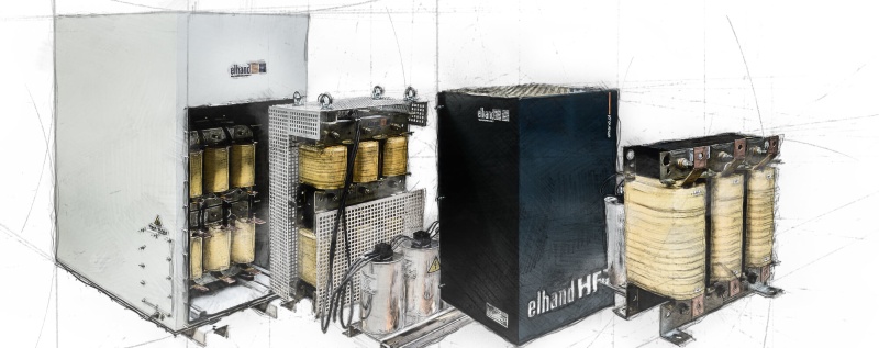
Filters
In currently used frequency converters the switching frequency of transistors reaches the value 15 kHz. The most commonly used type of transistors in these converters is the modern IGBT transistor which is characterized by a very short switching time. This results in high steepness of voltage du / dt at the inverter output. This may cause the appearance of wave effects in the cables supplying the motor, causing dangerous voltage rise on motor terminals, the occurrence of surges and the associated aging of insulation.
Application of the appropriate filter at the inverter output enables obtaining relevant sinusoidal currents and voltages, while significantly reducing the current flowing into the motor housing and protective PE conductor. When selecting the filter parameters it is important to take into consideration that the phase shift of currents and voltages before and after the filter should be as small as possible. If this requirement is not met then it would be imposible to acheive ideal inverter drive system operation, for example in system with flux-oriented control system or with direct control of motor torque system (dtc INVERTERS).


