Power supply construction
A significant part of devices requires to be supplied with direct current (voltage). In such cases DC power supplies are used. The power supplies usually consist of a network transformer, rectifying system and filter (depending on required coefficient of output voltage pulsation).

Functional diagram of DC power supplies
Description: Sieć – Network, Transformator – Transformer, Prostownik – Rectifier, Filtr - Filter
In the system of direct voltage (current) power supply transformer separates galvanically the supplied devices from network and supplies the rectifying system with voltage of appropriate values. These transformers have greater power (in relation to their dimensions) and absorb more current from network in comparison to ordinary transformers. At the same power returned to the load they have greater dimensions and absorb current of higher intensity.
Rectifying system converts the alternating voltage (current) into pulsating rectified voltage (current) with the constant component different from zero. This system uses semiconducting elements (diodes or thyristors), which are conduct the current unidirectionally.
The rectifying system is characterized by the number of pulses. It determines the number of non-smoothed pulses in the run of rectified voltage falling on one period of alternating supply voltage.
Therefore the rectifiers are divided into: 1; 2; 3; 6; 12; 24 - pulse.
The filter’s task is to limit the pulsation so that to receive an appropriate value of direct voltage and current in the receiver. In stabilized power supplies a stabilizer of direct voltage or current may be installed between the filter and receiver.
Układy prostownikowe, w zależności od struktury i liczby faz zasilającego napięcia przemiennego, dzieli się na:
- jedno
- wielofazowe.
Jeżeli napięcie podlega prostowaniu w czasie jednego półokresu każdej z faz, to prostownik jest nazywany półfalowym lub jednokierunkowym. Jeżeli natomiast napięcie prostowane jest w czasie obu półokresów, to prostownik jest nazywany całofalowym, dwukierunkowym lub mostkowym. Dodatkowy podział układów prostowniczych występuje ze względu na elementy z jakich został on wykonany:
- prostowniki niesterowane (diodowe)
- prostowniki sterowane (tyrystorowe lub tranzystorowe)
- prostowniki niejednorodne (zawierające zarówno diody jak i tyrystory lub tranzystory)
Najważniejsze wielkości charakteryzujące prostownik to:
- napięcie zasilania U2
- składowe stałe napięcia wyjściowego Uos i prądu wyjściowego Ios
- wartość skuteczna napięcia wyjściowego Uo
- dopuszczalny prąd wyjściowy Ios max
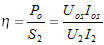
- sprawność energetyczna ηp, obliczona jako stosunek mocy prądu stałego na wyjściu do mocy pozornej prądu zmiennego na wejściu prostownika
- współczynnik tętnień kt, zdefiniowany jako stosunek amplitudy składowej podstawowej tętnień na wyjściu Uo1m i składowej stałej Uos
.png)
- maksymalna wartość napięcia wstecznego URm, które występuje na elemencie prostowniczym
Wielkości charakteryzujące prostowniki najłatwiej przedstawić za pomocą schematu oraz przebiegów napięć i prądów dla prostownika jednofazowego półfalowego z obciążeniem rezystancyjnym:
Prostownik półfalowy z obciążeniem rezystancyjnym ma bardzo małą sprawność (mniejszą niż 29%) oraz duże tętnienia. Oznacza to, że 71% energii pobieranej ze źródła jest tracona. Słabo jest wykorzystywany wówczas transformator sieciowy, przez który przepływa również składowa stała Ios prądu (powoduje ona podmagnesowanie rdzenia transformatora). Skutkuje to koniecznością użycia transformatora o większych wymiarach, niż wynika to z mocy wydzielanej w obciążeniu. W praktyce układ jednopołówkowy stosuje się rzadko, na ogół przy małych mocach.
Częściej stosuje się układy prostownicze dwupołówkowe, które mają lepsze właściwości. Ogólną zasadę działania prostowników dwupołówkowych przedstawia poniższy rysunek:
 |
|
 |
|
| a) | b) |
| Schemat prostownika dwupołówkowego z obciążeniem rezystancyjnym oraz przebiegi napięć i prądów: a) z wyprowadzonym środkiem uzwojenia wtórnego transformatora; b) w układzie mostkowym Graetza |
|
W obu układach prąd płynie przez obciążenie w jednym kierunku i ma charakter pulsujący. Obydwa układy mają większość parametrów identycznych. Jednakże w układzie mostkowym napięcie wsteczne na każdej diodzie jest dwukrotnie mniejsze, co umożliwia zastosowanie diod o mniejszym dopuszczalnym napięciu wstecznym. Mostek zapewnia też lepsze wykorzystanie mocy transformatora. Wadą jego jest konieczność użycia czterech diod.
Podsumowanie podstawowych parametrów jednofazowych układów prostowniczych z obciążeniem rezystancyjnym przedstawiono w tabeli:
| UKŁAD | PÓŁFALOWY | CAŁOFALOWY Z WYPROWADZONYM ŚRODKIEM | CAŁOFALOWY MOSTKOWY |
| składowa stała napięcia Uos |  |
 |
|
| wartość skuteczna napięcia na obciążeniu Uo |  |
 |
|
| sprawność energetyczna ηp |  |
 |
|
| współczynnik tętnień kt |  |
 |
|
| maksymalna wartość napięcia na diodzie URm |  |
 |
|

Zasilacz ELHAND typu EZ1-0,25 kVA; 400V±5%AC// 24V-7,5ADC
The 3-phase supply sources are used usually when the load currents are high. In such situations the multi-phase rectifying systems are applied. They can be divided into two basic types:
- unidirectional rectifying systems
- bidirectional (bridge) rectifying systems
In the first case the rectifying system, supplied from m-phase transformer, contains one diode in each phase, so the number of diodes is (m). All the diodes are directed consistently and their cathodes are shorted and connected with receiver’s terminal. Each phase conducts for 1/m of period, when the voltage value is higher than voltages of the remaining phases. As a result of that the current flows continuously in the load and it has a pulsating character.
In multi-phase unidirectional systems the voltage constant component on the load can be determined according to the following formula:

where:
- UOS – value of voltage constant component
- Uf – effective value of phase voltage (secondary winding)
- Ufm = √2 Uf – maximal value of phase voltage
- m – number of phases (m≥0)
The constant component increases with the increase of phase number. The dependence between UOS/Ufm relation and the number of phases in unidirectional rectifying system is presented in the table below:
| m | 1 | 2 | 3 | 4 | 6 | 12 | ∞ |
| Uos/Ufm | 0,32 | 0,64 | 0,81 | 0,90 | 0,96 | 0,99 | 1 |
The maximal and effective value of the phase current are as follows:
 ,
, 
Power efficiency:

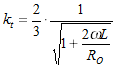
Pulsation coefficient is calculated in accordance with the following equation:
.png)
Several diagrams of unidirectional rectifiers with various output parameters. When selecting an appropriate system attention should be paid both to above-mentioned output parameters and economical reasons (cost of rectifier and supply transformer) and then the most optimal solution should be selected.

Fig. 1 Diagram of unidirectional, 3-pulse rectifier.
Description: Odbiornik - Receiver

Fig. 2 Diagram of unidirectional, 6-pulse rectifier.
Description: Odbiornik - Receiver

Fig. 3 Diagram of unidirectional, 6-pulse rectifier consisting of two 3-pulse rectifiers connected in parallel, through a compensating choke.
Description: Odbiornik - Receiver
In unidirectional systems the currents in transformer secondary windings, connected to a converter, flow only for a part of the period. Therefore the typical power of transformer exceed considerably the power value of the direct current circuit. In addition to that an unfavourable phenomenon of core magnetization, decreasing the efficiency of converter and the entire system, occurs in unidirectional systems. This phenomenon is caused by the constant component of secondary windings current. The 6-pulse system with a compensating choke is the most favourable in respect of transformer utilisation.
In case of the second type of multi-phase rectifying systems, i.e. in bidirectional (bridge) system each phase is connected with two diodes: one belonging to the first group (D1, D2 and D3) and one belonging to the second group (D4, D5 and D6). The current of load connected between linked anodes and cathodes of both diode groups, flows always through two diodes and two phases of transformer secondary winding. The voltage run on the load results from momentary values of phase-to- phase voltage. The current of each phase consists of two pulses with the duration 1/m of the period. The direction of their flow is opposite, so the phase current does not contain the constant component and does not cause the core magnetization. It allows to obtain better utilisation of transformer and bigger watt-hour efficiency ηp of rectifier. Mostly used bidirectional rectifying systems are presented below:

Fig. 4 Diagram of bidirectional 6-pulse rectifier in bridge system.
Description: Odbiornik - Receiver

Fig. 5 Diagram of 12-pulse rectifier, consisting of two bridge 6-pulse rectifiers connected in series.
Description: Odbiornik - Receiver

Fig. 6 Diagram of 12-pulse rectifier, consisting of two bridge, 6-pulse rectifiers connected in parallel through a compensating choke.
Description: Odbiornik - Receiver
6-pulse bridge system belongs to the mostly applied converting systems, mainly due to its most economical balance of costs and output parameters. In this system the apparent powers of converting transformer primary and secondary windings are equal and they amount to the lowest of values possible for 6-pulse systems.
The systems consisting of converters connected in series (Fig. 5) are applied in order to obtain high output voltages. The systems consisting of bridge converters connected in parallel (Fig. 6) are applied to supply the receivers characterized by consumption of high currents.

ELHAND power supply, type EZ3-50 kVA ; 400V±2x2,5%AC// 110V-427ADC; IP24
Filtration – improvement of rectifying systems output parameters
L and C reactance elements are used in rectifying systems in order to improve their properties. These elements fulfill two basic functions: they reduce the pulsation and store the energy when the value of rectified alternating voltage is high, in order to return that energy when the voltage is decreasing. These elements can be connected in two ways:
- capacitive – in parallel to the load,
- inductive – in series to the load.
Such solutions are applied mainly in rectifying systems which are characterized by disadvantageous suppression factor.
 |
|
 |
|
| a) | b) |
| Single-phase rectifying systems with resistance-capacitive load. Diagrams and runs of voltage and current: a) half-wave rectifier; b) full-wave rectifier Description: Odbiornik - Receiver |
|
Comparing to the systems with resistance load the rectifying systems with resistance-capacitive load are characterized by better efficiency and lower pulsation. These systems achieve the best properties at high values of load resistance (RO). Therefore they are applied within the range of relatively small powers, mainly in 1-phase systems, rarely in 3-phase systems.

Full-wave rectifier with resistance-inductive load.
The systems with resistance-inductive are usually of full-wave type, because it is hard to obtain a continuous current flow through the load in the 1-phase half-wave systems .
The constant component of the output voltage does not depend on the inductance.
Along with the inductance increase the pulsation factor decreases, so the share of variable components in the output voltage decreases :
When ωL/R0 relation increases then the output voltage run is approaching the ideal. The filtration properties of the rectifier with resistance-inductive load are improving also along with the load increase (IOS increases, RO decreases). Therefore such systems are applied for high load currents, mainly in 3-phase or 6-phase versions.
